FM signal settings section
All the settings to generate a compliant FM signal.
All the settings that are related to the FM signal can be found here, such as pre-emphasis, stereo and RDS encoding, RDS texts, Stokkemask (ITU-R SM.1268) and ITU-R BS.412 compliance and multipath distortion protection.
FM processing is more difficult that normal processing. Because of
Pre-emp you often loose highs when enabling the FM processing settings (
Composite Clipping helps a lot against this), Stokkemask and multipath distortion protection can have some impact on the amount of stereo separation, and BS412 lowers the level a lot.
Some people prefer to use Stereo Tool only for processing and use a separate RDS and stereo coder. While this works and still gives a reasonable sound, it makes it impossible to use
Composite Clipping which gives several dB's of extra headroom for mainly the high frequencies, and features such as multipath distortion protection. If the whole composite/MPX signal is generated from within Stereo Tool, the sound that can be generated is a lot better.
If you are planning to use Stereo Tool on an FM transmitter, please also read
FM Output. If you have multiple transmitters and want to synchronize the sound between them, see
Synchronize FM transmitters.
FM signal section
Extra FM pre/de-emphasis (bad!)
Perform extra pre-emphasis to protect the FM signal against overshoots after a lossy link.
Don't use this unless you know what you are doing. This setting will adversely affect the audio quality.
Adds extra pre-emphasis to the FM clipper on top of the FM pre-emphasis, to protect the FM signal that is sent to the transmitter against overshoots, and de-emphasises it again before outputting. If you have a clipper at the transmitter site, you probably don't want to use this. And you definitely don't want to use this at high loudness levels. In countries with BS412-like regulations, this setting can be useful though.
Pre-emphasis time
The amount of extra pre-emphasis to add to the FM pre-emphasis.
Main panel
Audio settings panel
More audio settings panel
Encode stereo panel
Stereo carrier settings panel
More stereo coder settings panel
RDS carrier settings panel
More carrier settings panel
General panel
- Enabled
Enables FM processing and features.
- Lowpass
Enables lowpass filter for FM.
This overrules the global lowpass frequency for the FM output.
- Lowpass filter
FM lowpass frequency.
Pre-emp panel
Pre-emphasis settings.
To reduce hiss on the receiver, FM stations broadcast high frequencies a lot louder, and the receiver reduces this again. If you don't configure pre-emphasis correctly, you'll get a very dull sound that lacks highs. So, if you don't hear enough highs on your FM station, this is where you should look first.
- Pre-emphasis
Enables FM pre-emphasis.
If this checkbox is enabled, processing (Advanced Clipper and Hard Limit output) is done with pre-emphasis.
If you want to send pre-emphasized output to a transmitter, make sure that Pre-emphasize output is also enabled!
- Pre-emphasis
The pre-emphasis setting for your region.
For most parts of the world this must be 50 μs, but in the US 75 μs is used. This means that the increment of high frequencies in the US is higher than in the rest of the world, which also means that it is more difficult to broadcast loud highs.
- Pre-emphasize output
Outputs a pre-emphasized signal.
If you leave this disabled and feed the signal to an FM transmitter, the sound will lack highs. Make sure that this is enabled when using an FM transmitter.
If this checkbox is disabled, processing (Advanced Clipper and Hard Limit output) is done with pre-emphasis, but signal that's sent to the output is de-emphasized, as it would be in an FM receiver. This means that you can hear the sound as it would be on a radio, but the signal is not suitable to send to a transmitter.
An exception is when the transmnitter performs pre-emphasis, but chances are that you'll get a pretty bad signal because in many cases the pre-emphasis circuit in a transmitter is non-phase linear, and it might not perfectly match the FM specification.
- Non-phase linear deemphasis
Compensates for a non-phase linear pre-emphasis unit after Stereo Tool.
If (and this is not recommended) you use the left/right de-emphasized FM signal from Stereo Tool to feed into a stereo coder that also pre-emphasizes (this can also be part of a transmitter), in many cases such pre-emphasis units are not phase linear. Combining phase linear de-emphasis from Stereo Tool with non-phase linear pre-emphasis in another unit causes overshoots. To compensate for those overshoots, use the non-phase linear de-emphasis mode instead.
Please note:
Using the Encode Stereo in Stereo Tool, especially when combined with the Composite Clipping, gives a far superior result.
RF spectrum analyzer panel
Shows the RF spectrum as it should look after broadcasting it with an FM transmitter.
The wider the signal is, the more disturbances your signal causes to weaker stations at adjacent frequencies. A wider FM spectrum also increases intermodulation distortion and reduces the received signal strength (beause a larger part of the spectrum will fall outside that range that a receiver is tuned to.) See
Stokkemask and
Multipath clipper.
Stereo panel
Stereo coder settings.
- Encode Stereo
Enables the stereo coder.
Requires a 192 kHz capable sound card.
- Pilot injection level
The stereo pilot volume, in % of the maximum level.
- Polar stereo (Eastern Europe OIRT band stations, 64-73 MHz)
Only to be used for Eastern European OIRT band FM stations.
You probably don't need this, if you do, you know what you're doing. Don't use this if you don't know what it is.
RDS panel
RDS encoder settings.
Encode RDS panel
- Encode RDS
Enables the built-in RDS encoder.
See RDS data for more settings.
- RDS injection level
The RDS signal volume, in % of the total level.
Higher values may improve RDS reception, but may also increase multipath distortion and make Stokkemask compliance much harder.
- Use quadrature mode for slightly more audio loudness
Encodes RDS in quadrature mode.
This lowers the total (top) of the stereo pilot and RDS signal from about 13.5 to 12%. Which allows about 0.15 dB extra loudness when not using the Composite clipping. With the composite clipper the difference is smaller, about 0.02 dB.
Drive panel
Composite limiter settings. Use Composite Clipping instead, it works much better.
- FM composite limiter overdrive
Controls the amount of composite limiting.
- MPX Oversampling mode
Always use 'ALWAYS', unless you're broadcasting an extremely weak hobby signal.
Force generate Composite even if no output
Always uses the Composite Clipping when it's enabled.
Normally, composite clipper is disabled if there's no sound card available that runs at 128 kHz or more. This enforces generating the composite signal anyway in that situation. Mainly useful for testing.
SCA section
Settings for extra analog audio channels.
On the FM band, it's possible to transmit extra analog audio channels, which can be used for example for audio transmission for the blind, music for stores etc.
These transmissions are normally modulated at 67 and/or 92 kHz. A special receiver is required to receive it.
Please note that broadcasting SCA channels will increase multipath distortion and that the required frequencies are very high for sound cards - the 92 kHz carrier cannot be transmitted completely at all.
SCA panel
The general SCA settings.
- SCA Channel 1 Enabled
Enables the 67 kHz SCA channel.
- SCA Channel 2 Enabled
Enables the 92 kHz SCA channel. This will not work properly!
- SCA 1 injection
The 67 kHz SCA channel level. Default is 20%.
- SCA 2 injection
The 92 kHz SCA channel volume.
- SCA 1 frequency
The center frequency to encode the SCA 1 injection SCA channel.
- SCA 2 frequency
The center frequency to encode the SCA 2 injection SCA channel.
- SCA lowpass
Lowpass frequency of the SCA channels.
If this is set too high, other subcarriers such as RDS at 57 kHz (+/- 2.4 kHz) may be affected.
BS412 section
Settings to control ITU-R BS.412 compliance.
In several European countries, FM stations have to comply to a standard called ITU-R BS.412. This standard demands that the total power over any 60 second period is below a certain threshold.
The BS412 limiter in Stereo Tool attempts to achieve this without compromising the audio quality. It does this using 20 different algorithms that predict future input based on previous input, which together decide what to do with the sound to keep it below, but as close as possible to, the threshold.
Despite of this, you get the best result if the input level is already nearly constant. The BS412 limiter in Stereo Tool knows how to handle increased highs due to pre-emphasis and slightly increased bass because other filters respond less to bass (due to ITU-1770). But other changes may cause problems. So try to avoid using the equalizer in the Multiband compressor and Bass Boost too much.
The BS412 graph shows output and filter effect levels in a single graph. The pre-drawn horizontal lines are 1 dB apart, the darker line on top is at 0 dB.
In the graph, you can see lines of different colors: BLACK shows the moving BS412 output level and should be below, but as close as possible to, the 0 dB line. RED shows slow volume changes. In general, it's best if this line doesn't drop below -1 dB - bigger drops can be noticeable. GREEN/PURPLE shows short-term volume drops caused by the compressor. YELLOW spikes show that the de-esser reduced loud highs. The actual drop of the highs is less than what is depicted here. BROWN spikes show the de-basser in action. Finally, PINK shows the dynamic adjustment of the compressor thresholds.
You can see the output for the last 5 minutes, the last hour or the last day. Use the "Large view" button for a bigger display, which also shows the maximum FM deviation at the bottom (top line is +/- 75 kHz, each horizontal line is 10 kHz less).
More BS412 settings panel
BS412 panel
The most important BS412 settings.
- BS412
Enables the BS412 limiter.
Input signal strength panel
BS412 input audio level.
- Drive
Amplifies or attenuates the input level before the BS412 limiter.
This value should be chosen to amplify or attenuate the audio level such that it is just above the BS412 target level, to avoid stress on the BS412 limiter. Red line drops should be limited as much as possible (preferably no drops below -1 dB) and the green/pink line drops should not get below -2 dB too often, but the black line should be as close as possible to 0 dB.
- Auto-adjust for target level
Target level panel
Deviations from standard BS412 values.
- Target maximum level (60 s)
Determines the maximum BS412 output level.
In most countries where BS412 is mandatory, this must be set to 0 dB, but in some it's +3 dB. When changing this setting, you may also need to adjust Drive.
- Max MPX deviation
Lowers the maximum MPX deviation when using BS.412.
If you have a sound card that's not perfectly linear, you can lower this slider a bit to lower the maximum peak level of the output. The Target level will still be reached, so this can be used to protect against 75 kHz overshoots.
Stations that want to sound smashed can lower this setting further to increase the amount of clipping.
Safety limiter panel
BS412 compressor settings.
- Dynamics
Controls the BS412 compressor target level, relative to Target maximum level (60 s).
Setting this higher means that the compressor kicks in later, but may result in bigger slow volume changes.
- BS412 Compressor upspeed
Determines how fast the volume level is increased when the output level is low.
When the output volume has been lowered due to too loud sounds, this slider determines how fast the output volume can be increased again. A higher value means that the average output level gets closer to the target level, but may also cause pumping. A low value may cause source material with big volume changes to come out too soft on average.
- BS412 Compressor downspeed
Determines how fast the volume level is decreased when the output level is too high.
When the output volume would be louder than the set maximum + , this slider determines how fast the output volume is reduced. A higher value means that drops faster. A low value may cause the volume to be too loud for a longer period of time.
- BS412 Remove remaining peaks above
Cuts off remaining peaks above this level.
The compressor responds slowly, this cuts off peaks that remain.
Slow response limiter panel
Controls the long-term limiter.
The long-term limiter adjusts the level very slowly based on 20 different prediction algorithms that predict future input. If the amount of limiting is less than about 1 dB (visible as a red line in the BS412 output display), it should normally not be noticeable.
Limiters panel
- Attack shape
Determines how fast the volume is dropped if it is too high
BS412 requires that the total volume stays below a threshold in any 60-second period. If the input level is too high (higher than Target maximum level (60 s)) at any moment, it needs to be dropped. If this is done fast, the drop will be less deep, but for short bursts it will be bigger than needed. If the drop is slow, and the loud sounds last for a longer period of time, the drop will get deeper because the first part which is too loud needs to be compensated. So, if you broadcast audio with rapidly changing volume levels, a lower value (say, 2) might work better, for normal music a value around 3 should be fine. If you're going to broadcast constant tones, go for a higher value :) .
- HF limiter threshold
Limits loud highs before the compressor.
Reduces loud (pre-emhpasized) highs before they hit the compressor. This filter only responds if the total level would be too high.
- LF limiter threshold
Limits loud bass before the compressor.
Reduces loud bass sounds before they hit the compressor. This filter only responds if the total level would be too high. controls if in case of loud bass the total level is reduced (causing pumping) or only the bass (causing less bass).
- Bass coupling
Chooses between bass reduction or pumping.
If the bass gets above the threshold set in LF limiter threshold, this slider controls if the entire volume should be dropped (causing pumping) or only the bass (resulting in less bass).
- Legacy compatibility mode (bad)
- Rise faster
Headroom panel
Determines how much headroom the BS412 limiter has for errors.
- Headroom
The amount of headroom.
If this value is too low, sudden big volume drops (red line) can occur, which are usually visible as a sharp very deep spike down. This causes a very brief drop in audio level, which must be inserted at that point because otherwise the signal would have gotten above the Target maximum level (60 s).
However, if you lower this value, the average output level will also be lower (of course, differences of 0.1 dB are not really noticeable).
Experimental settings panel
- Progressive rise on deep levels
- Use more linear level drop behavior
- Combine methods to determine rise speed (slower)
- Linear rise speeds, don't speed up as much if distance from target gets bigger
- Lower level more if output exceeds target
Time intervals section
Level per time interval panel
- 1 sec
- Adjust weight of latest 60 seconds
- Adjust weight of latest 30 seconds
- Adjust weight of latest 15 seconds
- Adjust weight of latest 7.5 seconds
- Adjust weight of latest 4 seconds
- Adjust weight of latest 2 seconds
- Adjust weight of latest 1 seconds
- Adjust weight of latest 0.5 seconds
- Weighed peak
- Predicted level
- Peak
- Predicted output
Time interval measurement effect panel
- Mix in time interval behavior
- Drop Down speed
- Drop Up speed
Hot Sound section
Hot sound panel
Quick adjust panel
Levels panel
- Drive
- Relative Threshold
- Safety compressor extra dynamics
- Knee
Limit panel
- Limiter
- Limit speed
- Relative limit time to the right
Speeds panel
Attack panel
Release panel
- Release speed
- Exponential Release
Ratio panel
Stokkemask section
ITU-R SM.1268 compliance settings.
The Stokkemask (ITU-R SM.1268) is a mask on the RF spectrum (see
RF spectrum analyzer). Enabling this mask makes the RF spectrum less wide, which improves multipath distortion and reception strength of your station, and reduces disturbances caused to weaker stations at nearby frequencies.
Using Stokkemask is mandatory in the Netherlands, but it improves reception everywhere. For stations that don't need to be compliant but do want the improved reception,
Multipath clipper can be used - it has less impact on the audio and the CPU load but it
should have the same advantages.
The Stokkemask filter can be used without using Composite Clipping, but the sound quality will suffer a lot, and the effects of the RDS and stereo pilot cannot be taken into account, which means that compliance cannot be completely guarranteed.
RF bandwidth limiter (ITU-R SM.1268, Stokkemask)
Enables Stokkemask clipping.
Stokkemask settings panel
Stokkemask CPU usage settings panel
- Allow overshoots
Don't stay within the mask, allow occasional spikes for better audio quality.
- Maximum RF bandwidth (< 0 reduces stereo, > 0 breaks compliance)
Make Stokkemask filtering more or less strict.
In countries where you have to comply to Stokkemask, this should never be moved up. But elsewhere, if you want to profit from the improved reception with less effect on the audio, you can move this slider to make the Stokkemask filtering more or less strict.
- Strictness (CPU)
Decreases the effect of the Stokkemask clipper by using more CPU power.
If this is set higher, multiple RF measurements are done to check if the Stokkemask clipper manages to get the signal inside the Stokkemask - once it does, the amount of Stokkemask clipping can be reduced, which also reduces the effect of the Stokkemask clipper on the audio quality and stereo separation.
- Use area (CPU)
CPU usage control setting.
Set this higher for slightly more accurate processing. The CPU load will increase a lot though.
- Legacy mode (bad, lower CPU)
Do not use this unless you CPU can't handle the new mode!
Legacy mode is LESS strict and has much more effect on the audio.
Warning: Changing this mode changes the output signal, if you are in a country where you have to be Stokkemask compliant, you might need to do a new measurement when you turn this setting off.
- Strict post filter (CPU)
Strict (but heavy) filter to remove any remaining overshoots.
FM reception optimization: RF bandwidth limiting panel
Enables Stokkemask clipping mode.
- Requires composite clipper
Stokkemask CPU usage panel
Settings that affect the Stokkemask clipping CPU usage and audio quality.
RF spectrum analyzer panel
Shows the RF spectrum as it should look after broadcasting it with an FM transmitter.
The wider the signal is, the more disturbances your signal causes to weaker stations at adjacent frequencies. A wider FM spectrum also increases intermodulation distortion and reduces the received signal strength (beause a larger part of the spectrum will fall outside that range that a receiver is tuned to.) See
Stokkemask and
Multipath clipper.
Composite Clipping section
Composite clipping greatly improves the quality of loud FM transmissions.
The composite clipper can create upto 160% left and right channel modulation while keeping the total modulation at 100%. It also allows the usage of Single Sideband stereo coding and several reception improvements.
If the audio is clipped normally, and stereo encoding and RDS encoding are added afterwards, the output that is generated will only rarely peak to the maximum modulation. Multiple dB's of signal headroom are wasted by clipping the audio without looking at the stereo pilot, RDS signal and how the L+R and L-R modulated at 38 kHz contribute to the peak level.
To give a simple example: If there's a high frequency peak in the audio, and both the stereo pilot and RDS signals are peaking in the opposite direction, then the peak in the audio could be clipped at a much higher level. It is possible to 'hide' audio peaks inside the holes created by the pilot and RDS signals. The effect of the 38 kHz modulation of the L-R signal is even bigger but also much harder to explain.
When using normal audio clipping and then adding the stereo and RDS signals, the left and right channel audio level after demodulation on an FM receiver will always be a bit below 100%.
FM composite limiter overdrive can get it closer to 100%, but it will never exceed 100%. When using composite clipping, values over 160% can be reached. The audio level coming out of the receiver still won't exceed 100% though, because only high frequencies can reach levels above 100%, and they are reduced with de-emphasis in the receiver.
The composite clipper can not be used if you are using an external stereo coder, and works slightly less good with an external RDS encoder.
Composite clipping panel
Composite Clipper settings.
- Composite clipping
Enables the Composite Clipper.
The composite clipper uses the Advanced Clipper, but uses a lot more CPU load.
- Requires stereo encoding
- Requires high sample rate output
- Extra drive
Extra Clipper drive when using composite clipping.
Because the composite clipper causes far less artifacts in the sound, it's usually safe to make the sound a bit louder. This slider allows you to do that without changing the normal Clipper drive level for when the composite clipper is turned off.
- Leif's clipper efficiency modification
Enables performance optimizations based on Leif Claesson's Omnia.9 clipper.
This greatly reduces the CPU load with no noticeable reduction in audio quality.
- Composite clipping Strictness (Leif) (CPU)
Similar to Composite clipping Strictness (CPU), used when Leif's clipper efficiency modification is enabled.
- True Peak precision (Leif) (CPU)
Determines how many clipper steps are oversampled to 768 kHz.
Only used when Leif's clipper efficiency modification is enabled. A higher value uses more CPU load, but it also sounds slightly better.
- Composite clipping Strictness (CPU)
Controls how strictly the clipper clips.
Lower values leave more small spikes in the output signal, which (if you don't want spikes) need to be removed by HARD LIMIT. And HARD LIMIT removes the spikes by lowering the output level. Strictness is configurable because higher Strictness levels cost much more CPU processing power.
The Advanced Clipper Strictness (CPU) setting is ignored when the composite clipper is active.
- Clip demodulated peaks
Don't allow too high peak levels in demodulated audio.
Some radios have a problem with very high demodulated peak levels. Without any reduction, they can reach levels over 160%. Since stations can also broadcast with too much (more than 75 kHz) modulation, a radio will always have some headroom - but 60% is just too much for some.
Such high spikes only occur occasionally, so clipping them at a lower level (110-130%) does no affect the audio much.
This increases the CPU load. Multipath clipper and Stokkemask have a similar effect (they keep the peak levels at around 120%), so it is probably better to use those.
- Maximum audio peak levels after demodulation
The level at which to clip the demodulated peaks.
See Clip demodulated peaks.
- Also composite clip low frequencies (CPU!)
Slightly increases the quality of low frequencies, at the cost of increased CPU usage.
For low frequencies, composite clipping has far less effect than for high frequencies, but it can still have some effect. With this checkbox enabled, the bass clippers also run in composite clipping mode.
- Also composite clip high frequencies (CPU!)
- Oversampled pre-clipping (CPU!)
Uses composite clipping mode for some preparation steps.
Before the actual clipping starts, a 'test' clip is performed to detect quality issues such as drops in other frequencies caused by loud highs. If this setting is disabled, this test clip is performed at a lower sample rate, which might slightly affect the result of the measurement.
- Single Side Band (SSB)
Enables Single Sideband encoding.
This video was published by Omnia:
Single Sideband (SSB) coding means that the stereo signal is encoded at the area between 23 and 38 kHz, instead of 23 and 53 kHz. This should reduce multipath distortion issues because there is less high frequency content.
Reports on the usefulness of this technique vary. Other manufacturers report numbers like 40% see an improvement, 40% see a deterioration, 20% sees no difference.
For now, if you want to improve multipath distortion, our suggestion is to use the Multipath clipper or Stokkemask - responses to that have been far more convincing. Of course you can also combine them.
- Single sideband
Select a single sideband encoding method.
When using Single Side Band (SSB), there are multiple methods to do it. They all may cause a different result, some were made to resemble what other manufacturers do, others were made based on our own ideas.
- Standard
This is how other manufacturers do it. Very low frequencies (upto about 150 Hz) are modulated normally, anything higher than that is modulated only on the lower sideband. - Probably optimal
Something special happens when a tone of 12666.7 Hz is transmitted in the L-R signal. The upper sideband frequency (50666.7 Hz) is exactly a multiple of the lower sideband frequency (25333.3). In the RF spectrum, the energy of these two frequencies gets bundled and much higher peaks occur.
If you have a tone at 1000 Hz, it will be modulated at 37000 and 39000 Hz. Switching to SSB modulation would create a twice as strong signal at 37000 Hz, which causes much higher peaks in the RF spectrum and seems more likely to cause reception problems.
Probably optimal mode reduces frequencies above 50667 Hz more, but leaves lower frequencies as they are (dual sideband modulated). - Steep optimal
Similar to Probably optimal, but with a much steeper filter at 50666 Hz. - Extreme (Pure Hilbert)
For testing purposes only, do not use this. Uses perfect SSB modulation. Causes reception problems in receivers and lower audio levels in the clipper.
- Multipath clipper
Enables a clipper mode that's intended to reduce multipath distortion.
Multipath clipper mode combines ideas from a previous multipath clipper implementation and Stokkemask. It probably reduces multipath distortion.
- Multipath clipper level
Chooses between more multipath distortion protection and better sound quality.
A higher value allows more spikes in the RF signal that could cause multipath distortion, but also affects the audio less.
Because the effect on the audio is already very limited, a value of 100% is usually fine.
"Rules are made to be broken" - Louder! panel
"Opportunistic SSB/DSB switching", which reduces the amount of clipping and allows for more loudness, more dynamics and a cleaner sound.
Dual sideband stereo (DSB) and single sideband stereo (SSB) have peaks at different locations. So, for some moments in time, SSB will result in having less clipping, and at other moments, DSB will result in having less clipping.
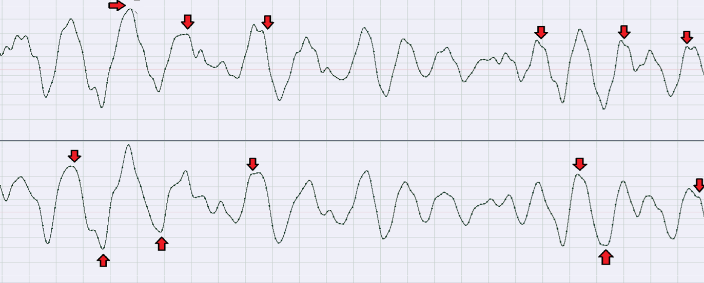 Single sideband peaks vs. dual sideband peaks.
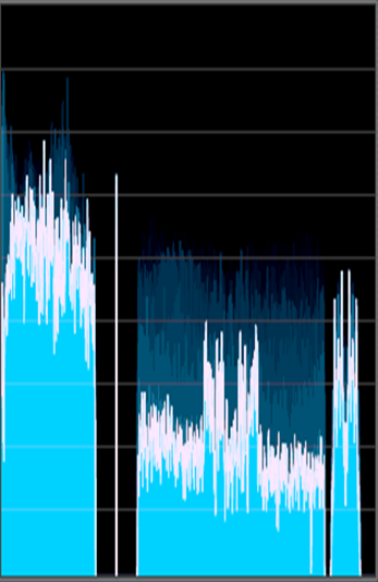 The effect of using this option on the spectrum.
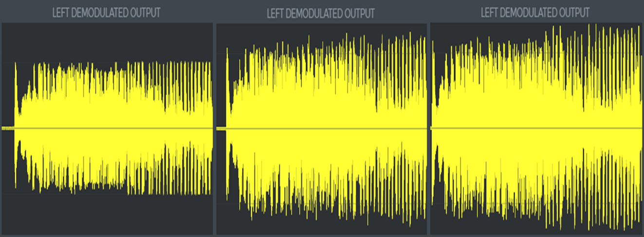 Audio peak levels after demodulating the audio. From left to right: Traditional left/right clipping, composite clipping, composite clipping with L-R asymmetry.
- L-R asymmetry
Enables "opportunistic SSB/DSB switching"
- Extra L-R asymmetry steps (more CPU)
Determines amount of opportunistic switching analysis vs. CPU load.
Higher is better.
- Allow L-R asymmetry
The maximum amount of asymmetry in the L-R part of the MPX spectrum.
Some receivers might not like large amounts of asymmetry. We have not really encountered issues with it (the effect is far smaller than that of using SSB stereo), but this setting makes it possible to limit the effect.
Multipath Stereo Phase Difference Remover panel
Controls stereo effects that can cause phase cancellation, to reduce multipath effects on FM and improve mono compatibility.
Current data panel
- Current PI code
- Current PS text
- Current RadioText
- Latest ClockTime
RDS data section
The detailed RDS settings.
These settings determine the texts that are displayed on a receiver including dynamic texts such as the current song name, automatic switching to Alternative Frequencies, broadcasting the current time and date and more.
RDS panel
Detailed RDS settings.
Basic visible data panel
- PI code
The PI code of your radio station.
The PI code controls things like automatic switching to Alternative Frequencies,. It's important to set this up correctly. Here's why: - If you use the same code as another station in your area, you might 'steal' listeners from them (they automatically switch to your station if its reception is better), or you might loose listeners to them in areas where their signal is better. Beside this, this is extremely annoying to listeners.
- If you change your code at a later time, some radios where your station has been programmed on a preset button may turn the sound off because they 'think' it's the wrong station, even if reception is perfect. Only reprogramming the preset button helps in that case - but no all listeners will understand this.
PI codes are regulated differently in different countries, please check with your local authorities what you need to do.
The PI code needs to be entered as a hexadecimal number. The default is FFFF, which means that it should be disabled - but not al receivers adhere to this.
The first 2 digits of the PI code are a country code, but again, many receivers ignore it. Whatever you do, make sure that the last 2 digits are unique in your area, and that they are not FF.
- PS text
The Program Service text (8 characters)
According to the original RDS specification, the PS text should be static, and its intended use is to display the station name. However, most stations use this text to broadcast lots of things beside the stations name, such as traffic information, phone numbers, even advertisements. Please be aware that certain receivers - mainly in cars - do not display quickly changing texts because it is seen as a danger because it could distract the driver.
Stereo Tool can broadcast a constant (not changing) text, as is officially mandated by the RDS specification, but it also supports a lot of extra features such as alternating texts, scrolling texts, and dynamically inserted texts such as the name of the current song.
Note that the RDS transmission speed is very low (at most 22 characters per second), so building up the texts can take some time. Because the RDS signal is very weak, bad reception, especially for (moving) car radios, often leads to missing parts, which means that - even when the reception is good - texts need to be transmitted at least two times to be displayed. Many radios even ignore texts (or portions thereof) that are not transmitted at least two times. This lowers the effective transmission speed to 11 characters per second. So it can take a lot of time before all the texts are displayed properly. The line is also shared between different types of data (PS text, Link error '9043', Transmit ClockTime, ...). Stereo Tool's RDS encoder contains an automatic priority mechanism, which lets texts that have just been changed take more bandwidth.
The descriptions below are valid for both types of texts, although some (such as scrolling) are not useful for RadioText due to the slow transmission speed.
Many radios can only display a limited set of characters: Basically the letters A-Z (capitals/upper case only!), the numbers 0-9 and some special characters such as /, \, -, < and >. This is mainly an issue for PS texts, because they are also displayed on cheap LCD displays on car radios. So especially for PS texts, only use the characters listed above. (Lower case characters are automatically converted to upper case by all the receivers that we tested).
Constant texts
To transmit a constant text, just type that text in the appropriate field (PS Text or RadioText) in the interface.
The PS Text must be at most 8 characters, the RadioText can be up to 64 characters. Any extra characters are ignored.
Example:
POWER-FM
Alternating texts To show different alternating texts, write all the texts you want to be displayed in the appropriate field in the interface. Split the different parts with a / character.
Example:
POWER-FM/88.5 FM
(Note: The . character will be replaced by a space on radios that cannot display a .)
By default, every part of the text will be displayed for 5 seconds.
Changing the timing of alternating texts To change the amount of time a text is displayed, put the requested time in front of the text, as follows: - 1.5s:POWER-FM
Displays the text POWER-FM for 1.5 seconds. When specifying a time in seconds, Stereo Tool will automatically make sure that the text is transmitted at least twice so radios can receive it properly, even if that takes longer than the specified time.
- 3t:POWER-FM
Transmits this text 3 times. Stereo Tool will transmit this text 3 times, then switch to the next text. Note that it is possible to use 1t here, but it will lead to bad reception on many radios.
Example:
3s:POWER-FM/1.5s:88.5 FM
Displays POWER-FM for 3 seconds, then 88.5 FM for 1.5 seconds.
Scrolling texts
Due to the slow transmission times, scrolling is only useful for PS texts. Transmitting a PS text takes at least (2 transmissions * 8 characters / 22 characters per second) = 0.72 seconds. (For RadioText that's 2 * 64 / 22 = 5.8 seconds, which makes scrolling useless.)
For left scrolling, add a < character at the front of your text. To scroll at higher speeds, add multiple < characters. Right scrolling is also possible, use > for that.
Examples:
<THE BEST HITS IN TOWN
<<THE BEST HITS IN TOWN AT HIGH SPEED
3s:POWER-FM/1.5s:88.5 FM/<THE BEST HITS IN TOWN
The scrolling speed can also be adjusted using timing settings:
3t:<<THE BEST HITS IN TOWN
In the previous example, the first and last characters are displayed only very briefly. There are two possibilities to solve this.
Adding spaces:
3t:<< THE BEST HITS IN TOWN (ends here)
But it's also possible to specify different timings for different monents of the scrolling. That makes it possible to display the start and end longer than intermediate parts.
Instead of using just 2s: which sets the display time for every part of the scrolling, different values can be set for different positions.
During scrolling, the first position is called '1', the second '2' etc. The last position is also known as '-1', the one before that as '-2', etc.
So what you want is to display positions '1' (start) and '-1' (end) for 1.5 seconds, and everything in between (2 up to -2) should be broadcast 2 times (the minimum for good reception). That can be done as follows: 1=1.5s,2..-2=2t,-1=1.5s:
Examples:
1=1.5s,2..-2=2t,-1=1.5s:<THE BEST HITS IN TOWN
3s:POWER-FM/1.5s:88.5 FM/1=1.5s,2..-2=2t,-1=1.5s:<<THE BEST HITS IN TOWN
Word wrapping texts
Instead of using scrolling, you can also use word wrapping. That way you can type a longer text, and the words will all be displayed separately.
Word-wrapping is enabled by adding two pipe || characters.
Example:
||THIS TEXT IS WORD WRAPPED
Again, it's possible to adjust the time that a word is displayed:
1.5s:||THIS TEXT IS WORD WRAPPED
If a word does not fit on the display (for PS texts if it's longer than 8 characters), the remaining characters are truncated. To avoid that, you can combine word wrapping with scrolling.
Combining word-wrapping and scrolling
If you combine word wrapping with scrolling, every word in a text is displayed separately. If it does not fit on the display, scrolling is used to display the whole word.
Example:
||<TRANSMISSION IS A LONG WORD
Now the scrolling problem from before re-appears: The start and end of the word are displayed only very briefly. This can be solved using the timing settings described for scrolling.
So, to display the text, every word 1.5 seconds, but if a word scrolls its start (1) and end (-1) should be displayed 1 second, and the parts in between (2 up to -2) should be broadcasted 2 times, that leads to: 0=1.5s,1=1s,2..-2=2t,-1=1s:
Example:
1.5s,1=1s,2..-2=2t,-1=1s:||<TRANSMISSION IS A LONG WORD Including dynamic texts
Dynamic texts can be used to include all kinds of changing information in your RDS texts. For example the name of the song that's currently playing, the current temperature, the weather forecast, you name it.
Stereo Tool enables you to include this type of data, as long as you can make the text available in a file. If you have that, there are 4 ways of including data from a file into your RDS text:
- \R"C:\Filename.txt"
Reads raw (unformatted) text from C:\Filename.txt, converts it to capitals, and inserts it here in the RDS text.
- \r"C:\Filename.txt"
Similar to \R, but does not convert the text to capitals. So - if your input file contains lower case characters - chances are that some radios won't display (parts of) the text.
- \F"C:\Filename.txt"
Reads formatted text from C:\Filename.txt, converts it to capitals, and parses it as if it were a part of the filled-in RDS text. So any special characters (<, ||, : etc.) are used for formatting.
Only use this if you know what you are doing, unexpected special characters in the file can lead to unexpected behavior.
- \f"C:\Filename.txt"
Similar to \F, but does not convert the text to capitals. So - if your input file contains lower case characters - chances are that some radios won't display (parts of) the text.
Unless you are doing special things, you should only need \R.
Example:
POWER-FM/PLAYING/\R"C:\NowPlaying.txt"
The texts are read from disk each time when the sequence repeats. So only use a local disk, then everything gets cached. If you use a remote disk, the program might still until it can access it. Do not use a network disk!
Because of this, there are 10 seconds between the moment when the file is read and the moment when the contents of the .txt file start to be transmitted. To avoid that, place the dynamic part at the start of the sequence - it repeats anyway:
\R"C:\NowPlaying.txt"/POWER-FM/PLAYING
Because song names can be long, you'll probably want to use the word wrapping and scrolling trick described above:
1.5s,1=1s,2..-2=2t,-1=1s:||<NOW PLAYING \R"C:\NowPlaying.txt" ON/6s:POWER-FM
How to get the name of the current song in a file?
If you are using Winamp, I recommend the Advanced mIRC Integration Plug-in (AMIP Now Playing) plugin for this. It can be configured to write the current song info to a file, and you can control the formatting of the song info - and which info is exactly written to disk.
After installing AMIP, configure it (it can be found under General Purpose plug-ins in Winamp). Enable "MAIL Integration", select a file name to write to, and select a format string in the Now playing edit box. %name gives you the name as Artist - Track. %s gives you the name as specified in Winamp (see General Preferences -> Titles), here you can remove the dash (-) if you want to.
Let's say you want to use scrolling for the entire artist/track name, including the dash. Then the steps to take are: - Install AMIP
- Configure AMIP: Enabled MAIL Integration, make sure that Now playing is set to %name.
- In Stereo Tool, type something like: 5s:POWER-FM/<<NOW PLAYING \R"C:\amip.txt"
That's all! For other programs, you'll need to find another way to write the current track info to a file. |
|
Special characters
As you can see above, some characters have special meanings in Stereo Tool. More specifically, the characters <, >, |, :, / and \ cannot be used normally in a text.
If you need to use any of these characters, put a \ in front of it. So: \<, \>, \|, \:, \/ and \\.
Example:
\<POWER!\>
- Windows-1252 input
Texts are entered using the standard Windows ASCII table.
Converts special characters, assuming that they are entered using the standard (Windows-1252) character mapping.
If this is disabled, characters are transmitted unchanged - so then it is assumed that the RDS character set is used.
- RDS RadioText on
Enables broadcasting the RadioText.
- RadioText
Configures the RadioText text that is displayed on some radios.
RadioText is a longer (upto 64 characters) text. Not all radios that can receive and display RDS also display this text.
RadioText can be configured using the same formatting as PS text. Because it takes a long time to transmit the (much longer) RadioText, upto about 5 seconds for a single transmission of the whole text, options such as scrolling are not very useful, and because the text is so long and reception errors frequently occur, it's better to avoid dynamic texts - unless there's a lot of time for each text to be transmitted (at least 20-30 seconds).
Stereo Tool also support RadioText Plus (RT+). With RT+, you can tell the receiver what the meaning of parts of the RT text is. For example, you can indicate that a part of the text is the artist name or title of a song, or a link to a website. Some receivers can use this info to - for example - display album art, or even direct links to buy a song. Receivers that don't support this will just ignore the extra information.
An RT text can contain at most 2 RT+ fields. To indicate the start or end of an RT+ field, use \+XX to indicate the start of a field, and \- to indicate the end. XX can either be the decimal value of the RT+ field (00-63), or one of our predefined names (AR for artist, TI for title, WW (case insensitive) for a link. The \+ and \- fields are not part of the length of the RadioText string!
Example:
Now playing \+tiRadar Love\- by \+arGolden Earring\-
For more info go to \+WWwww.thimeo.com\-!
- PTY
The type of program that you're broadcasting.
Many receivers can automatically search for some type of broadcast, such as a news broadcast. If you don't always broadcast the same type of program and you want to update this setting, make sure that Dynamic PTY is enabled.
The list of PTY codes is very different for RDS (EBU, used in Europe) and RDBS which is used in the US. The PTY codes are changed when you change the Pre-emphasis.
- Dynamic PTY
The PTY changes regularly.
- Send PTYN
Enables sending of the PTYN text.
- Send PTYN text
Text field to specify the PTY in more detail.
This can be used to transmit an 8-character PTYN text that will be displayed on receivers, usually instead of the PTY code. For example, the PTY code, which needs to be selected from a (limited and sometimes outdated) list of 31 entries, might be SPORT. And the PTYN text could then be FOOTBALL.
Receivers will still filter based on the PTY value.
Traffic info (TA/TP) panel
- Traffic Protocol (TP)
Traffic Protocol: This radio station broadcasts Traffic Announcements (Traffic Announcement (TA)).
- Traffic Announcement (TA)
Traffic Announcement: Currently traffic information is being broadcast.
Receivers will switch to this station, even overriding other audio sources such as CD's, USB sticks, memory cards and cassette tapes, and adjust the audio volume. Make sure to turn it off when the announcement is finished!
- Use TA timeout
Automatically turns TA off after Turn off TA after.
If for some reason TA is not turned off, this will turn it off automatically after some time.
- Turn off TA after
The timeout after which TA is turned off automatically.
- Sending TA now
Display whether the TA flag is set in the transmission.
Display only!
Basic metadata panel
- Music
RDS Music flag.
- Artificial Head
RDS Artificial Head flag.
- Compressed
RDS Compressed flag.
- Transmit ClockTime
Broadcasts the current date and time, once per minute.
A receiver can use this to adjust its clock.
- UECP is connected
Lights up when a UECP server is connected.
Advanced RDS panel
"Advanced RDS" features.
Advanced RDS is a separate license option. The main reason why there's a setting for this (it's easy enough to just not enable any RDS features that require an Advanced RDS license) is that external commands via
Enable UECP can also enable Advanced RDS features, which could cause a station to suddenly be in unregistered mode. So, turning this off also blocks external commands that use advanced features.
The following features are part of Advanced RDS:
Extended Country Code (ECC),
Language code,
Emergency Warning System (EWS) value,
Program Item Number (PIN),
Group sequence and
Extended group sequence,
AF B multiple,
EON and multiple
UECP (Remote) ports or Site/Encoder addresses.
- Allow UECP to enable features that require an Advanced RDS license
Enables Advanced RDS.
See Advanced RDS.
- Allow using features that require an Advanced RDS license
Additional remote inputs panel
2nd UECP input panel
3rd UECP input panel
4th UECP input panel
- ECC on
Enables transmission of the ECC code.
- Extended Country Code (ECC)
Sets the ECC code (hex).
- Language code on
Enables transmission of the language code.
- Language code
Sets the language code (hex).
Advanced metadata panel
Advanced RDS license panel
- EWS on
Enables transmission of the EWS (Emergency Warning System) code.
Do not use this unless you know what you're doing. This is part of the Emergency Warning System which is used in some countries. Special receivers are placed in homes that sound an alarm in case of a disaster (nuclear disaster, forest fire, ...).
- Emergency Warning System (EWS) value
Sets the EWS ID (hex).
- Program Item Number (PIN)
Enables transmission of the PIN (Programme Item Number).
The scheduled broadcast start time and day of the month is transmitted with this. This way, a receiver can see when a specific program starts and ends. It can for example be used to record a program, even if the start/end time changes (like VPS for video recorders).
- Day
The Program Item Number (PIN) day of the month.
- Hour
The Program Item Number (PIN) hour of the day.
- Minute
The Program Item Number (PIN) minute of the hour.
Group Sequence panel
- Enable Group Sequence
Enables the RDS Group Sequence.
The Group Sequence can be used to specify exactly which RDS groups must be transmitted in what order, and what should be transmitted if a specific group isn't available.
- Group sequence
The group sequence to be transmitted.
Example: 0A 2A 0A 8A
This will transmit a lot of 0A (PS text) groups, and only a small number of 2A (RT text) groups. 8A is normally used for TMC (traffic information for navigation systems), but it's only available if 8A group data is sent. See also Extended group sequence.
- Extended group sequence
Extended Group Sequence information.
Example: 8A: 3A 1A
If in Group sequence, group 8A is encountered but no 8A data is available, then this list means that it needs to try to transmit a 3A group. If there's also no 3A data, then it should transmit a 1A group.
Multiple such fall-through lists can be separated with a / . (Example: 8A: 3A / 9A: 1A).
AF section
RDS Alternative Frequency settings.
AF lists are used to tell a receiver which other frequencies carry the same content as the current frequency. Receivers can use this to automatically choose the frequency with the strongest signal. It can also tell receivers (together with some other data) which other frequencies usually carry the same content, but not always - and protect against switching to a different version of the same programming during times when the broadcasts are different. For example, a station might have multiple transmitters with regional ads or regional news.
Alternative Frequencies (AF) panel
Selection of the AF method.
- AF method
Selection of the AF method: A, B or B for retransmission on multiple frequencies.
AF method A is simple: You can select upto 25 frequencies that carry the exact same content. A receiver can always switch between these frequencies.
AF method B makes it possible to specify which frequencies carry the same content, and which frequencies carry localized (sometimes different) versions of the same content. A receiver should not switch (depending on settings that the user can sometimes overrule) to a frequency that carries a localized version of the same station, at moments when the content is different from the frequency that the user is listening on.
AF method B for retransmission is a special case: If the content of a station is rebroadcast elsewhere where there is no separate RDS encoder available, then the first station needs to transmit the AF method B lists for multiple stations. This feature requires the "Advanced RDS" license.
AF method A shared frequencies panel
The AF method A frequency list.
- RDS Alt Freq {}
List of upto 25 alternative frequencies.
Some radios use this list to check which other frequencies to scan for a stronger signal. However, most radios seem to rely solely on the PI code.
AF method B tuning frequency panel
The AF method B tuning frequency.
- Tuning frequency
The AF method B tuning frequency.
For AF method B encoding, the RDS encoder needs to know the frequency that the signal will be transmitted on. So, fill in your own frequency here.
AF B Same section
The list of AF method B frequencies that carry the same content.
RDS AF method B - Same program panel
The list of AF method B frequencies that carry the same content as Tuning frequency.
AF B Regional section
The list of AF method B frequencies that carry a regional variant.
RDS AF method B - Regional variants panel
The list of AF method B frequencies that carry a regional variant of Tuning frequency.
AF B multiple section
Settings for transmitting multiple AF method B lists.
RDS AF method B - Multiple lists (Advanced RDS) panel
Settings for transmitting multiple AF method B lists.
See
AF method.
- Main
The AF method B tuning frequency.
For AF method B encoding, the RDS encoder needs to know the frequency that the signal will be transmitted on. So, fill in your own frequency here.
- Same
List of frequencies that carry the same content as Main.
Example: 90.1 91.5 93.2
- Regional
List of frequencies that carry regional variants of same content as Main.
Example: 95.5 96.6
EON section
Enhanced Other Networks.
Enhanced Other Networks (EON) panel
Enhanced Other Networks settings.
- Transmit EON data
Enables EON transmission.
- Filter UECP PSN
Filters EON data based on PSN numbers in UECP (Remote) data.
EON settings panel
- Enhanced other networks (EON)
- Enable
Enables transmission of this line of EON data.
Note: No EON data will be transmitted if the PI code is not set, either via this interface or via UECP (Remote).
- PSN
PSN filter value.
The UECP (Remote) data with this PSN value will overrule the settings in the user interface.
- PI
EON PI code.
- PS
EON PS text.
- PTY
EON PTY value.
- Send PIN
Enables transmission of EON PIN data for this channel.
- PIN
EON PIN code.
- TP
EON TP setting.
- TA
Current EON TA value.
See also 14B burst.
- Send link
Enable EON link value transmission for this channel.
- Link
EON link value.
- AF
List of EON AF frequencies.
Several EON AF methods can be used and combined here.
Method 4 is used for AF method A data, and looks like this: "4 91.1 92.2 93.3". The number of frequencies can be anything upto 25.
Methods 5, 6, 7 and 8 are used for AF method B pairs, and are entered as the method number plus 2 frequencies in the correct AF method B order. So, if you want to transmit 2 pairs using method 5 and 6, you might type "5 91.1 92.2 6 94.4 93.3".
- 14B burst
Enables 14B burst transmissions when the TA value changes.
RDS remote control and monitoring panel
UECP (Remote) section
UECP settings.
UECP is a standardized protocol that is used to send information to RDS encoders. It is supported by many software and hardware RDS encoders, and by many playout systems.
Originally, UECP was used over an RS232 connection, but many products are now supporting it via Tcp/IP. Stereo Tool only supports the latter.
Enable UECP
Enables remote RDS control via UECP.
If this is enabled but no UECP server is connected, then the behavior depends on Use standard RDS settings when connection closed.
Mode
Switches between UECP (recommended!) and ASCII mode control.
UECP is a standard created by the same group that created the RDS standard, and we recommend using that when available.
However, some playout systems and other programs don't support UECP mode, and they support different dialects of an ASCII mode.
ASCII mode has been tested with Arctic Palm Center Stage Live RDS. At the moment it does not work with Magic RDS (we will fix that).
If you want to use ASCII mode, here are some example commands:
Set a static 8-character PS text:
PS=HELLO
PS HELLO
PS:HELLO
Set a dynamic PS text, automatically split into sub-texts if longer than 8 characters:
DPS=Hello there, this is a long text!
Alternative names: PS_TEXT, DYNPS, DPS1.
Set a dynamic PS text, automatically split into sub-texts if longer than 8 characters:
DPS=Hello there, this is a long text!
Alternative names: PS_TEXT, DYNPS, DPS1.
Set a Thimeo-style PS text, with instructions for scrolling, timing etc:
THIMEOPS=1s:Hello/2t<This text scrolls
Set an RT text:
RT=This is my radio station
Alternative names: TEXT, RT_TEXT, DYNRT, RT1, NEWS.
Send RT+ data:
RT+=a,b,c,d,e,f
Alternative names: RTP, RTPLUS.
Delete RT+ data:
RTPRUN
Other commands:
PI=1234
PTY=11
DI=0
MS=1
TCP/UDP
Listen to UECP in TCP or UDP mode.
Port
The UECP HTTP port address.
Packets
Packet counter (display only).
This can be used to verify that UECP data is coming in, and passing through the Site/Encoder filtering.
Advanced RDS license panel
Specific address panel
Listen only to UECP commands targetted to this address.
UECP can send commands via multicasting to multiple RDS encoders. If it does that, it can use addressing information to target a subset of encoders.
- Specific address
UECP "Specific Address".
See UECP specification and UECP encoder settings.
- Filter
Enables filtering for Site address(es).
- Allow traffic for site
UECP "Site Address".
See UECP specification and UECP encoder settings.
- or
- Allow traffic for Encoder Address
UECP "Encoder Address".
See UECP specification and UECP encoder settings.
- DSN
UECP "DSN".
See UECP specification and UECP encoder settings.
- PSN
UECP "PSN".
See UECP specification and UECP encoder settings.
Use standard RDS settings when connection closed
Determines behavior when the connection to the UECP server gets lost.
If this setting is enabled, whenever the connection is lost, the RDS encoder will return to the settings that are configured inside Stereo Tool. If it is disabled, it will keep using the last received UECP data.
If you are using UECP to update things like Now Playing information, you should probably enable this and configure some standard text inside Stereo Tool.
Monitoring section
Overview of transmitted RDS groups.

